
Nu-Way corporate website

DfM with Nu-Way Industries: Advice for Common Sheet Metal Forming Issues
Welcome to the first installment of a new blog series “DfM with Nu-Way Industries,” our tips and tricks for designing exceptional sheet metal products. As experts in precision metal fabrication, we understand the challenges that come with turning a concept into a manufacturable part with optimal fit, form, and function. That’s why we’re sharing practical insights to help you navigate the complexities of sheet metal design and ensure your designs result in efficient production processing.
In this first installment of the series, we’re focusing on one of the most critical aspects of working with sheet metal: considerations in forming. From understanding bend radii to managing features near bend lines, we’ll cover what you need to know to create designs that are both functional and efficient to manufacture.
Sheet Metal Forming: An Overview
One benefit of using sheet metal for products is its adaptability to a wide range of applications. Sheet metal can be easily profiled in the flat using punching or laser cutting processes and then formed using press brake tooling.
While sheet metal is flexible, it’s important to consider its forming limitations during the design phase to avoid issues in production, wasted materials, and higher costs.
Consideration: Inside Bend Radius

A component’s inside bend radius significantly affects its strength, appearance, and manufacturability.
Our Advice: Use Material Thickness as a Guide
A safe rule of thumb is to keep the inside bend radius no smaller than 25% of the material thickness; a bend radius of 30% to 50% of the material thickness generally works well with most common sheet metal materials and still achieves the design look you want.
This ratio may vary slightly depending on the material alloy, as softer materials can typically tolerate tighter bends. Harder alloys, however, usually require a bend radius equal to or greater than the material thickness to avoid surface fracturing or other bend failure.

Consideration: Larger Bend Radii
While larger bend radii may be necessary for specific applications, achieving them can introduce challenges, such as tolerances that are more difficult to hold and slower processes that increase the part cost.
Our Advice: Use Specialized Tooling or Bump Bending
Larger radii typically require specialized tools, which are less precise compared to single-hit tools used for tighter bends. The challenge here involves maintaining tight tolerances; larger radii make it more difficult to achieve tolerances as tight as ±0.010”, often settling for tolerances around ±0.015” to ±0.020”. This difference is generally acceptable since large radii are often used for aesthetic purposes rather than functional precision.
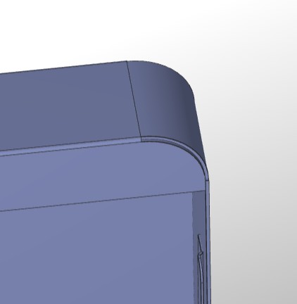
When larger radii—6 inches or more, for instance—are needed, single-hit tooling isn’t practical. Instead, our team will deploy a technique called bump bending. This method incrementally forms the desired radius by making multiple smaller bends with a smaller radius tool across the bend plane. While effective, bump bending is more time-intensive and incurs higher costs due to the increased number of hits and processing time required to produce the desired radius. Depending on the material used, the desired thickness, and the number of bump hits, there can be some witness marks from this process that may or may not be desirable. Some of those witness marks can be reduced by grinding the formed surfaces, but again, this requires time and skill to produce.
Consideration: Flanges and Features Near Bend Lines
Flanges and features located too close to bend lines can distort during sheet metal forming, leading to defects and additional rework.
Our Advice: Maintain Proper Distance from Bend Lines
Flanges should extend at least four times the material thickness from the bend line to allow for proper engagement with the bottom forming die. The same rule can be applied to any feature, like holes or cutouts placed near a bend line, to prevent deformation during bending.
Our Advice: Find Additional Work-Arounds
However, when features like holes and cutouts must be positioned near bend lines, additional strategies are needed to ensure the part forms properly, including:
- Relief cuts: Adding relief cuts around these features that extend through the bend. That way, when the part is formed, the bottom tools avoid the cutout area, ensuring clean and accurate bends.
- Backer strips: Using a secondary part, or backer strip, made of the same or stronger material provides support during the bending process. While effective, this method increases costs due to the need for additional setup time.
- Secondary processes: Adding features separately after the bend is complete if they can’t be managed during forming. While this avoids distortion, it increases handling time and costs, making it a less desirable option for high-volume production.
Design for Success with Nu-Way
Effective sheet metal design requires a deep understanding of the sheet metal forming process and the potential pitfalls that come with it. By incorporating our advice during the product design phase, you can minimize issues, reduce costs, and ensure high-quality results.
At Nu-Way Industries, our team specializes in helping customers navigate these challenges. Our expertise in making sheet metal products ensures your parts are designed for manufacturability, quality, and functionality.
Ready to get started? Partner with Nu-Way to take full advantage of our contract manufacturing and engineering services.